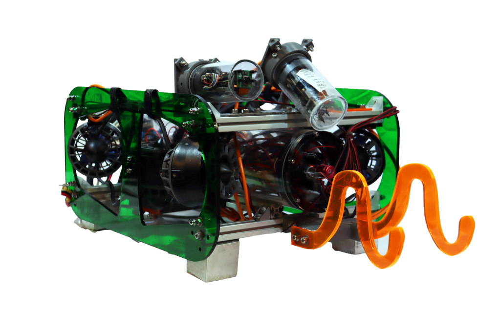
This week I had two main goals: Fix S.T.E.V.E. ROV and refine the ESC PCB I designed for the Robotics Team’s new ROV. I originally planned on starting to design a power distribution board this week, but I realized that the ESC PCB I had made was in serious need of some cleaning up. My top priority this week was fixing S.T.E.V.E.

It turns out, though, that fixing S.T.E.V.E. wouldn’t take very long. I am proud to say I could give the ROV a shining “It works!” after only five minutes of fixing. The primary reason for this is that our lead programmer’s (and pilot) computer was having “issues”. When we first plugging the ROV in a week ago, we couldn’t connect to it, but it wasn’t because of anything wrong with the ROV. This is because there was nothing wrong with the ROV. I spend all of five minutes plugging it in, scanning it’s IPs, and verifying that everything works perfectly fine. Our programmer couldn’t connect to it because his computer apparently spontaneously breaks and he didn’t realize this was the case.

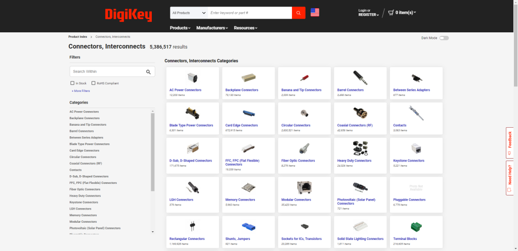
I spend almost all of Wednesday re-finding some parts on Digikey that I intend to use on the ESC PCB. A while ago I had downloaded some 3D models and have been using them in my PCB design, but I never saved the part ID. Without the part ID, I can’t actually buy these parts, so it’s pretty important. I had to search through Digikey in order to find the exact parts I was using while not knowing the specific details of each component such as Pitch or Contact Finish. I did eventually find the parts, though.


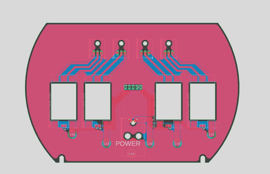
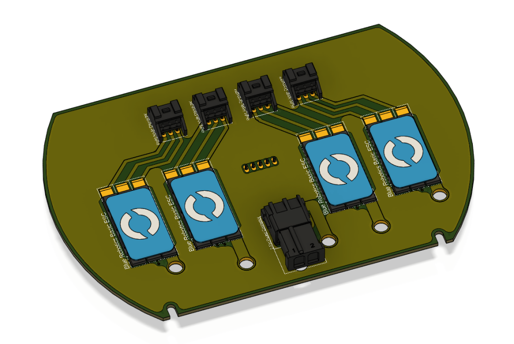
As I said, these parts would be used on the ESC PCB I’ve been working on. This past week, I added the signal connector, which I had not done yet, added groundplane on both sides of the PCB, and moved some on the connectors. The groundplane was a recommendation by Shane, someone introduced by Mr. Christy who is giving me advice on PCB design. The groundplane should hopefully isolate the signal traces from the high-frequency pulsing of the ESC output traces. Without it the signal might have too much interference and it wouldn’t work.
The silkscreen I added is not technically required, but it’s free with PCBWay and it will make my PCBs look almost professional. It will also help with assembly. Fusion 360’s way of doing silkscreens is kind of horrible, as I can’t directly edit the silkscreen of the PCB, I can only edit it for individual parts. I’ll have to come up with a solution to add some text to the PCB that isn’t for a specific part.
