This week I redesigned the ESC PCB with all of the knowledge I learned from my first attempt.


This new version will address the two main problems with the ESC PCB v1. The primary thing that is different is the connectors. This version will use XT30 connectors, which should hopefully have a lower resistance. I also had a chance to remake my footprint of the Blue Robotics ESC. I learned that I need far less clearance then I thought I did, so the ESC can be packed together closer. This allow the power input and signal connectors to be places away from each other and not overlap. Their overlapping made connecting and disconnecting the signal connector very difficult.
Unfortunately, we won’t be able to order these PCBs until our parts for them have arrived. I don’t know for sure that my footprints of the 3-pin XT30 connectors are good, so I need to test them before we commit on this new ESC PCB design.

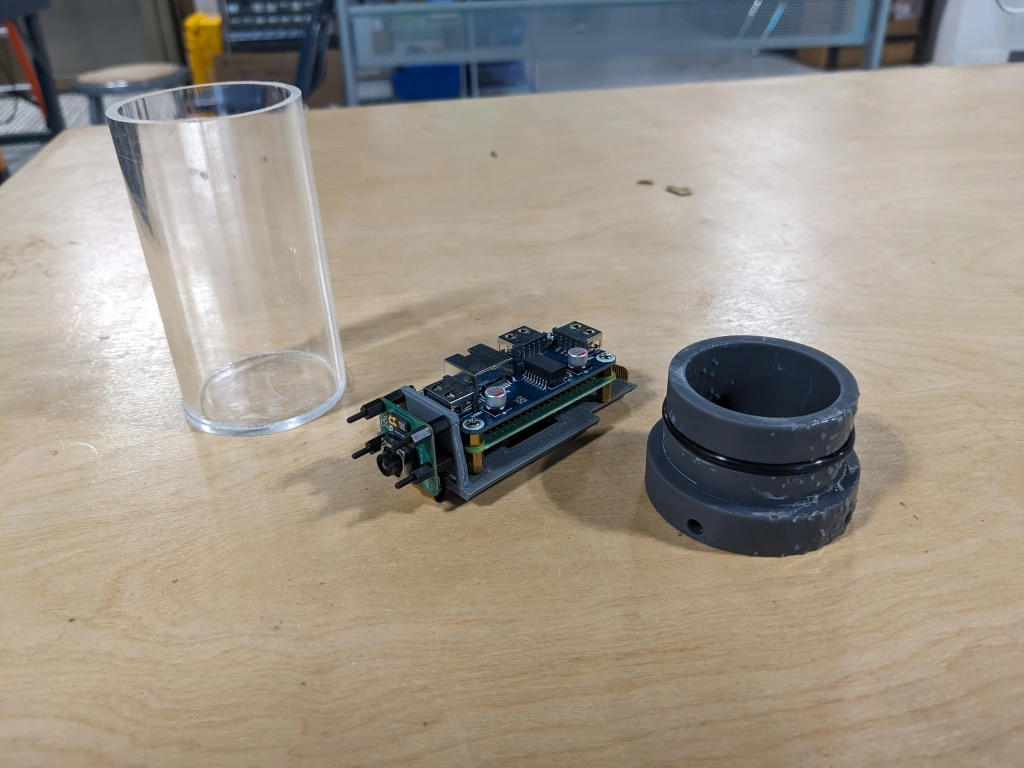
I also began building JONA’s second Tube Camera.
