Sunk Robotics:

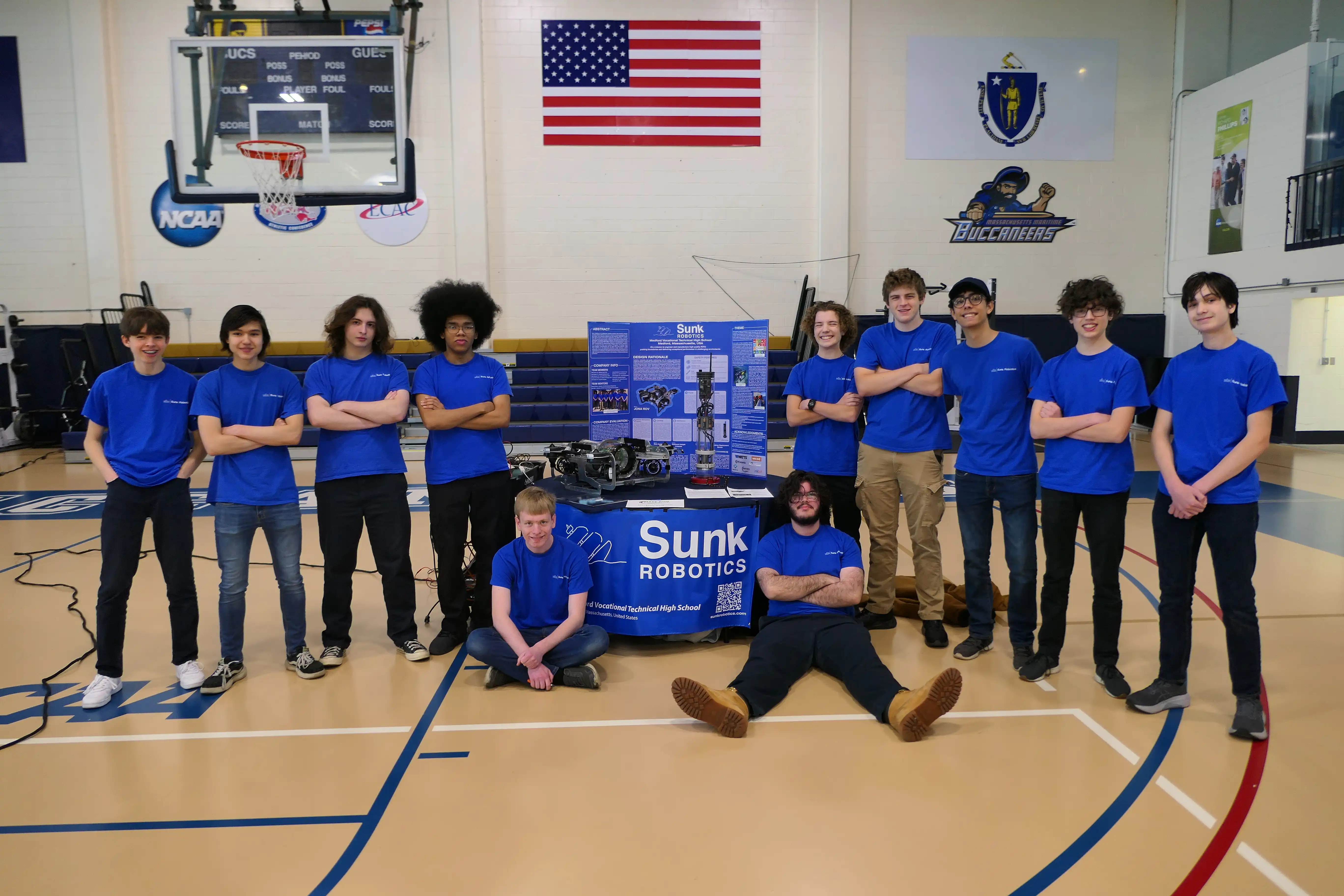
Left-to-Right: Miles Hilliard (‘27), Matthew Harris (’24), Noah Gibson (’24), Franklin Soto-Ortiz (‘24), Aaron BenDaniel (’25), Zachary Bertocchi (’24), Benjamin Wirz (‘25), Scott Campbell (‘25), Benjamin Santanna (‘24), Jonas Wirz (‘27), Timothy Hunt (’27).
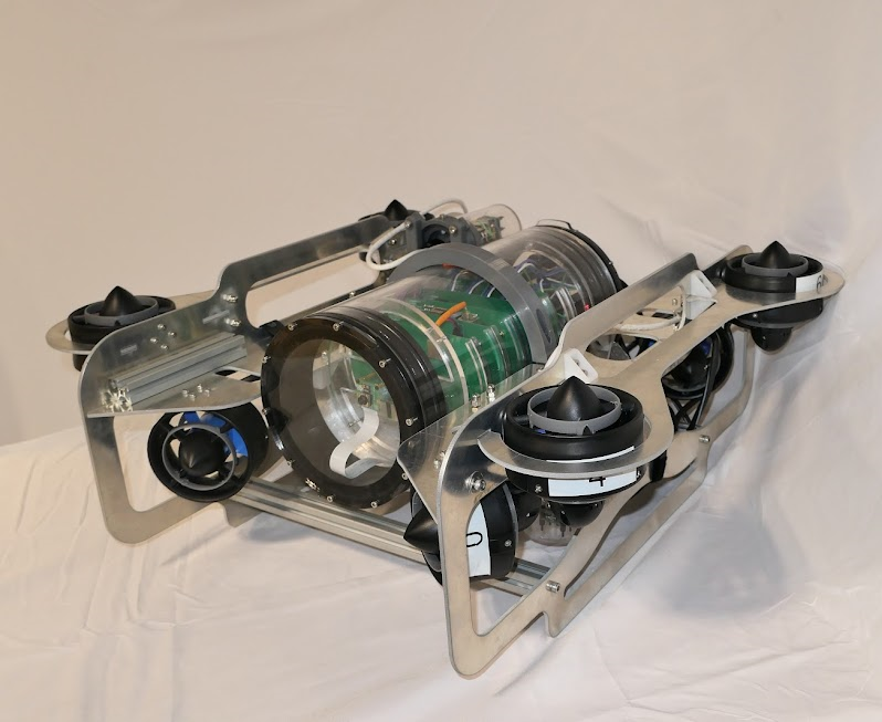
JONA ROV, Sunk Robotics’ newest edition to its fleet
I am a founding member of the Medford Robotics Team. Named Sunk Robotics, we participate in the Ranger class of the MATE ROV Competition. The MATE ROV Competition is an international underwater robotics competition that challenges students of all ages to build, operate, and speak about underwater remotely operated vehicles (ROVs). Sunk Robotics participates in the Ranger class, which is for high school-age teams and have advanced to the international level three times (2022, 2023, and 2024).
I primarily help with building and maintaining the hardware of our robot. I worked on the electrical and camera systems for our 2022 & 2023 ROV, S.T.EV.E., and the camera, electrical, and mechanical systems for our 2024 ROV, JONA.
Projects from Sunk Robotics:
2023-2024
JONA ROV Frame:
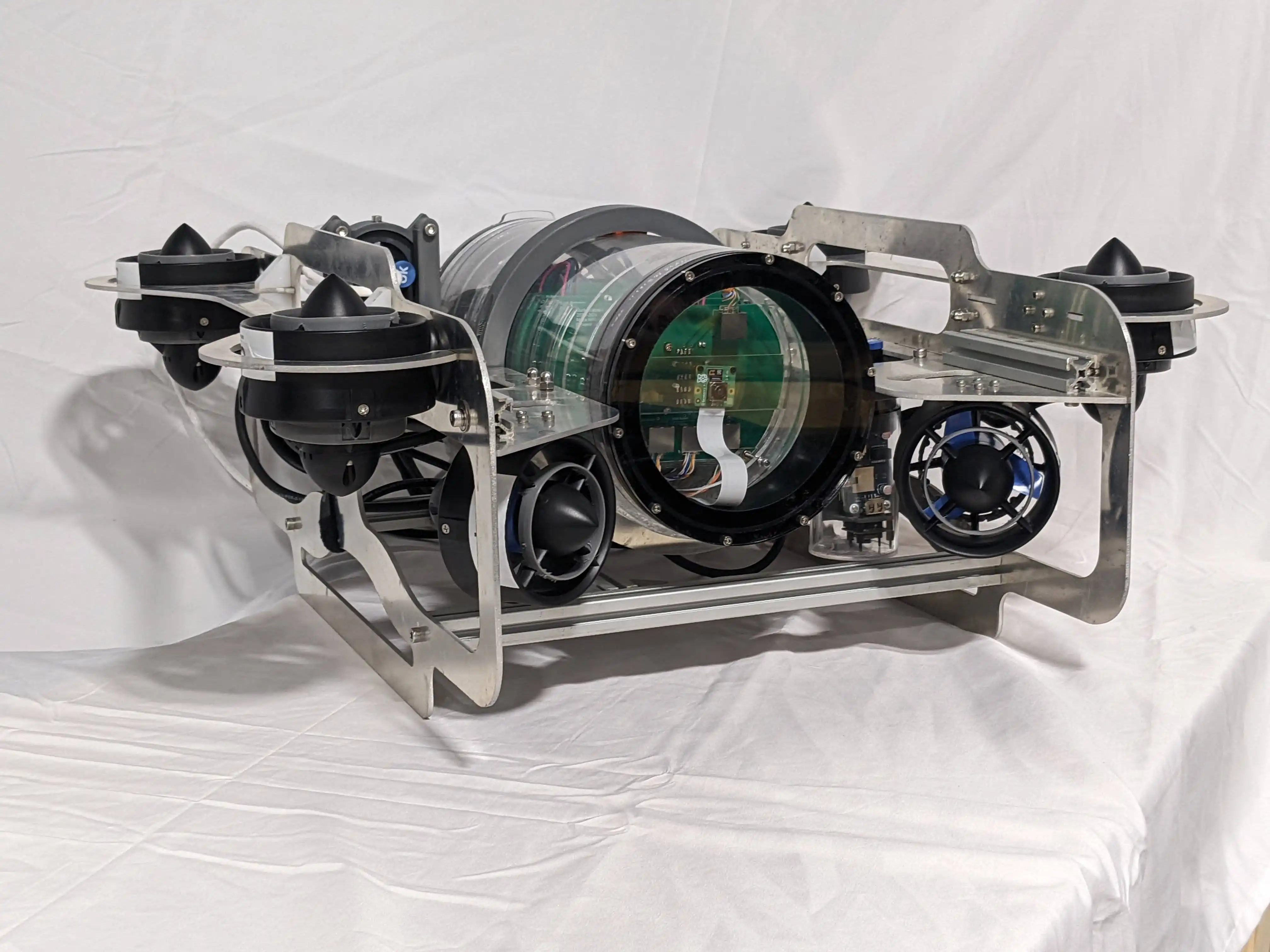
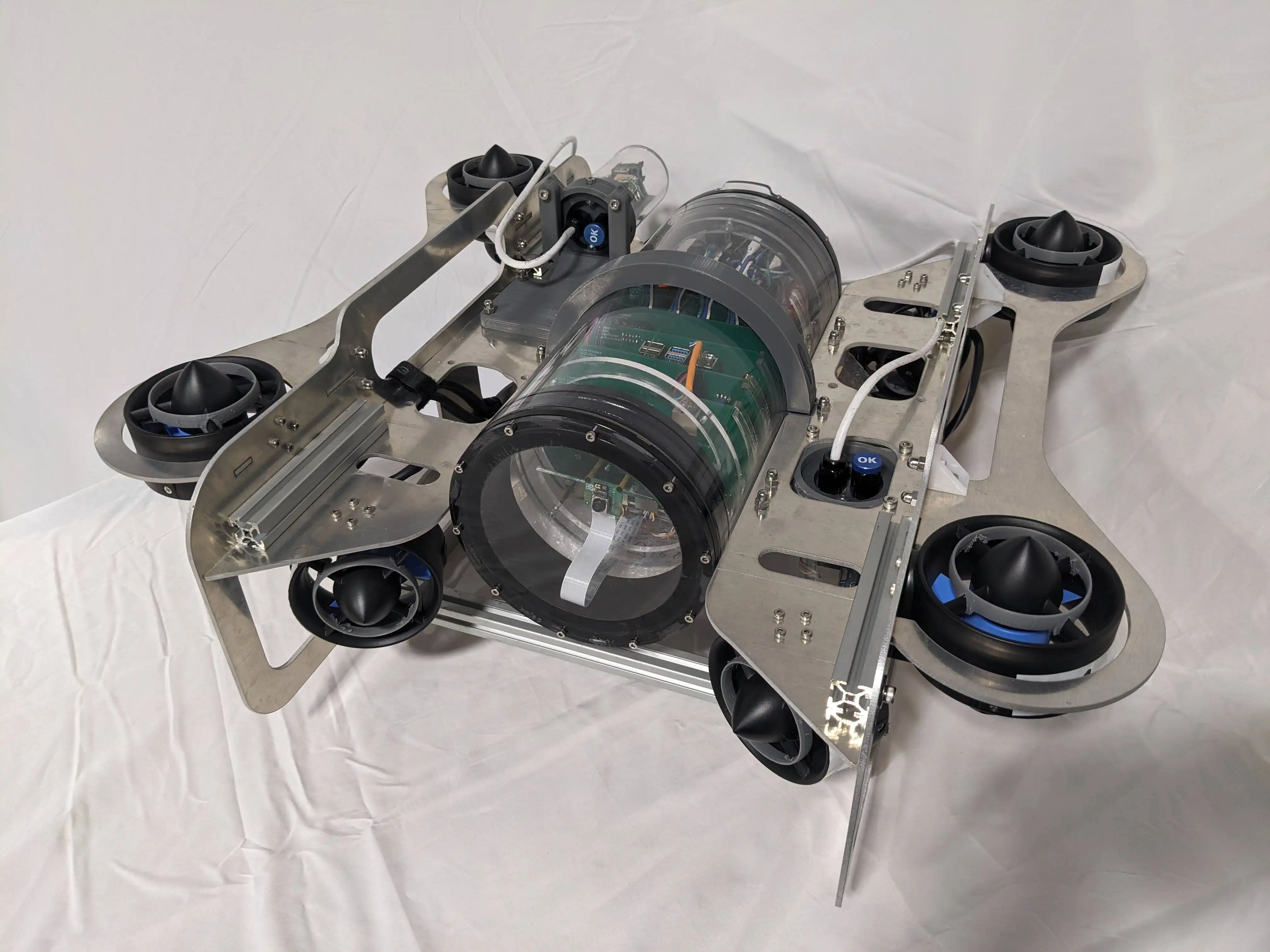
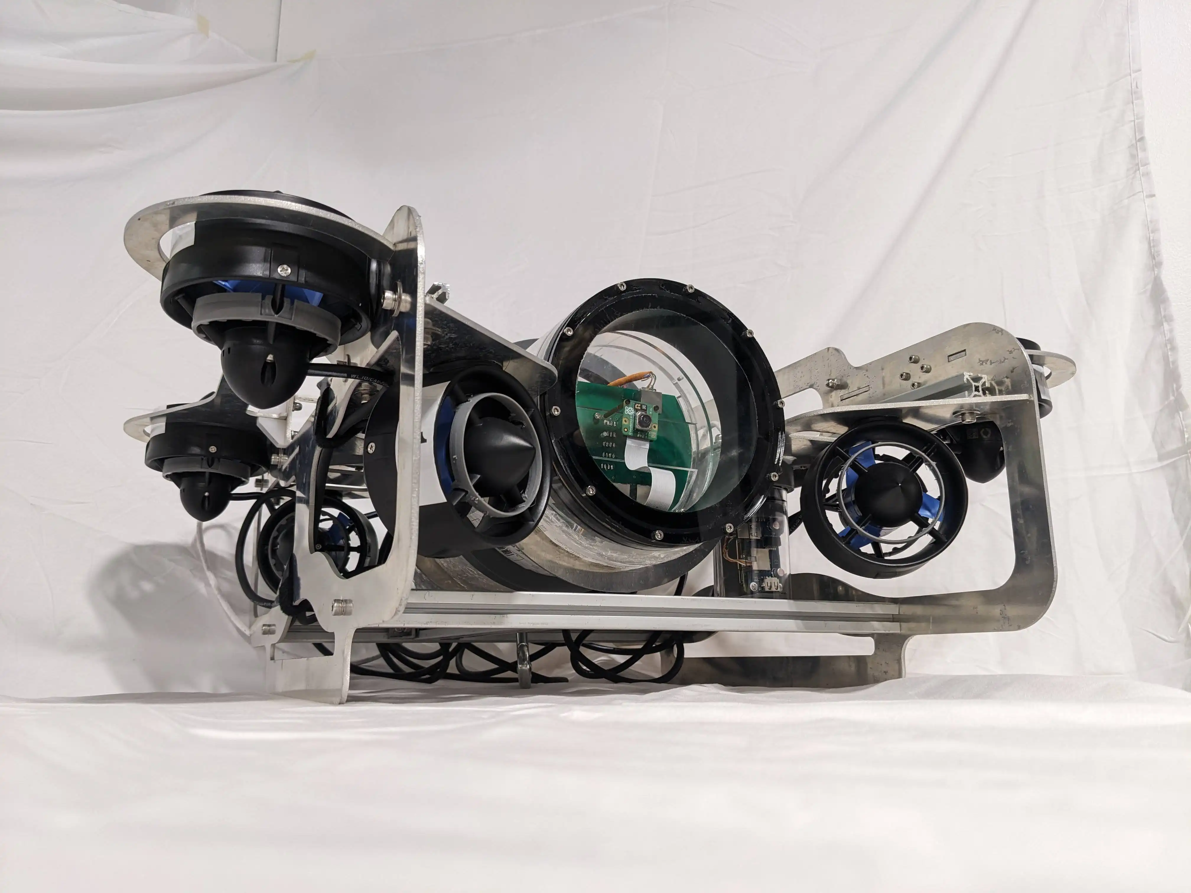
For our 2023-2024 year, Sunk Robotics decided to build an entirely new ROV Frame. The major reason for this was to increase our thruster count from 6 to 8. The additional thrusters will allow for far greater lift capacity and pitch control.
See posts about the JONA ROV Frame
JONA ROV Electronics Enclosure:
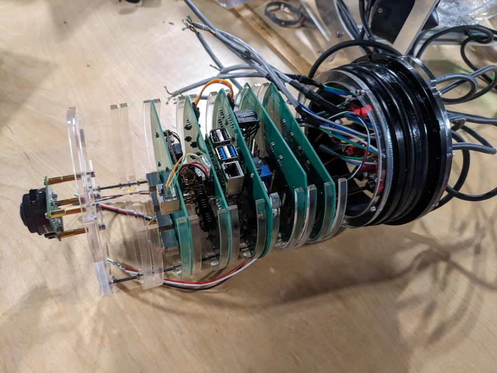
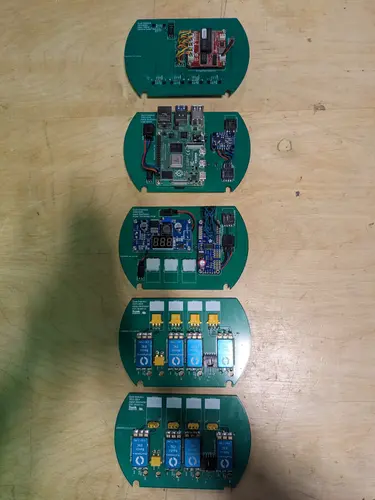
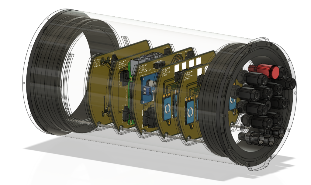
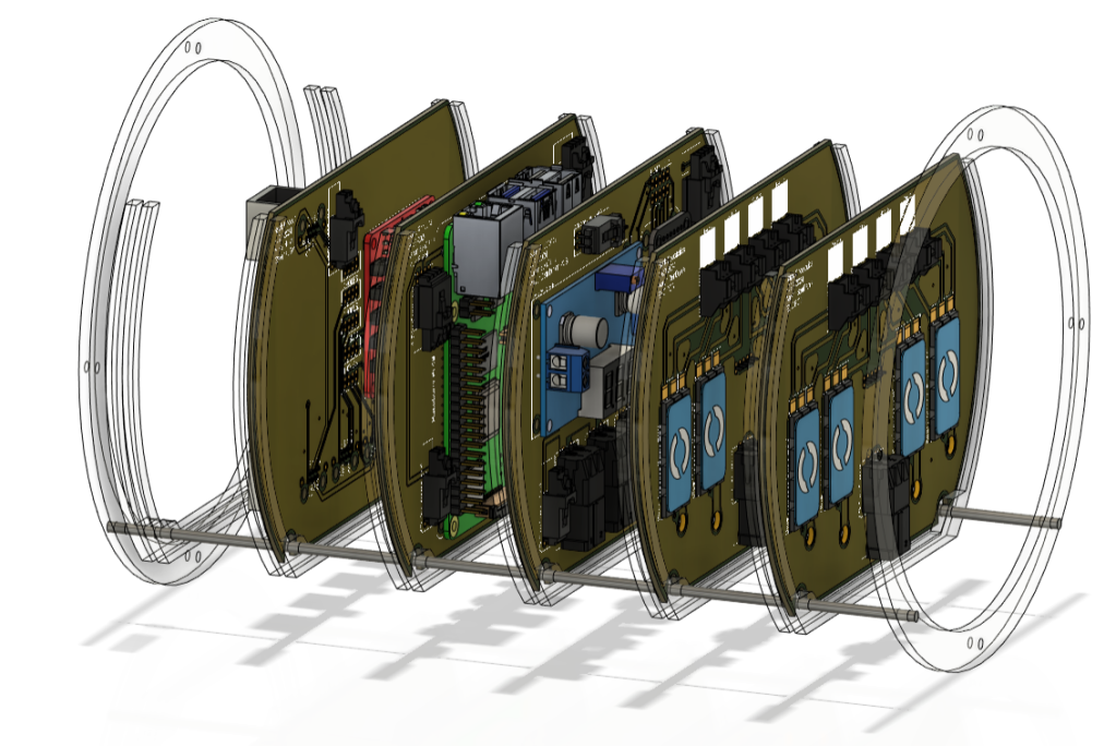
For our 2023-2024 year, the Robotics Team decided to switch from a 4in tube to a 6in tube. Redesigning the frame was the perfect opportunity to do this. Changing the size of our tube required a redesign of our electronics system. We wanted to transition away from a literal wooden plank and instead wanted a cleaner and more professional solution. Our new design features a frame that holds up to 6 custom PCBs. This new design is far cleaner than our previous design, much more reliable, and looks… safer.
See posts about the JONA ROV Electronics Enclosure
Watts Water Plaque:
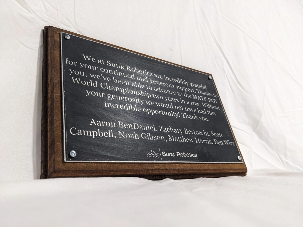
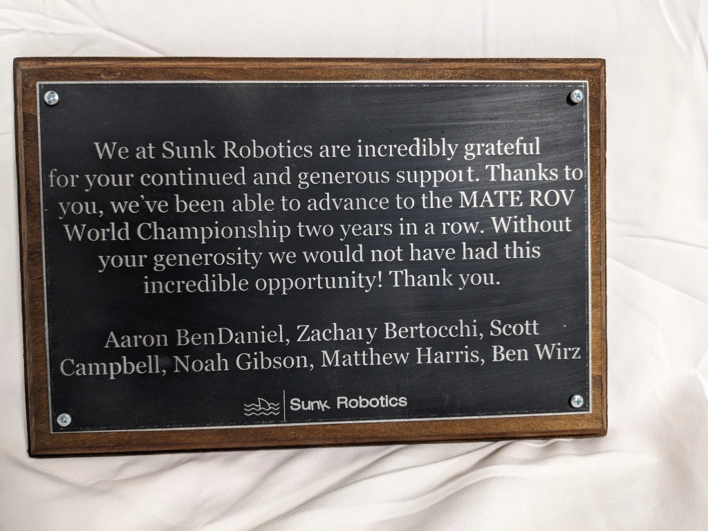
Our biggest cooperate sponsor, Watts Water Technologies, has continually supported Sunk Robotics, and we felt the need to express our appreciation. I took on the task of designing a gift for them and decided on a plaque that could have text engraved on it.
See posts about the Watts Water Plaque
Tube Camera – The Single Cable:
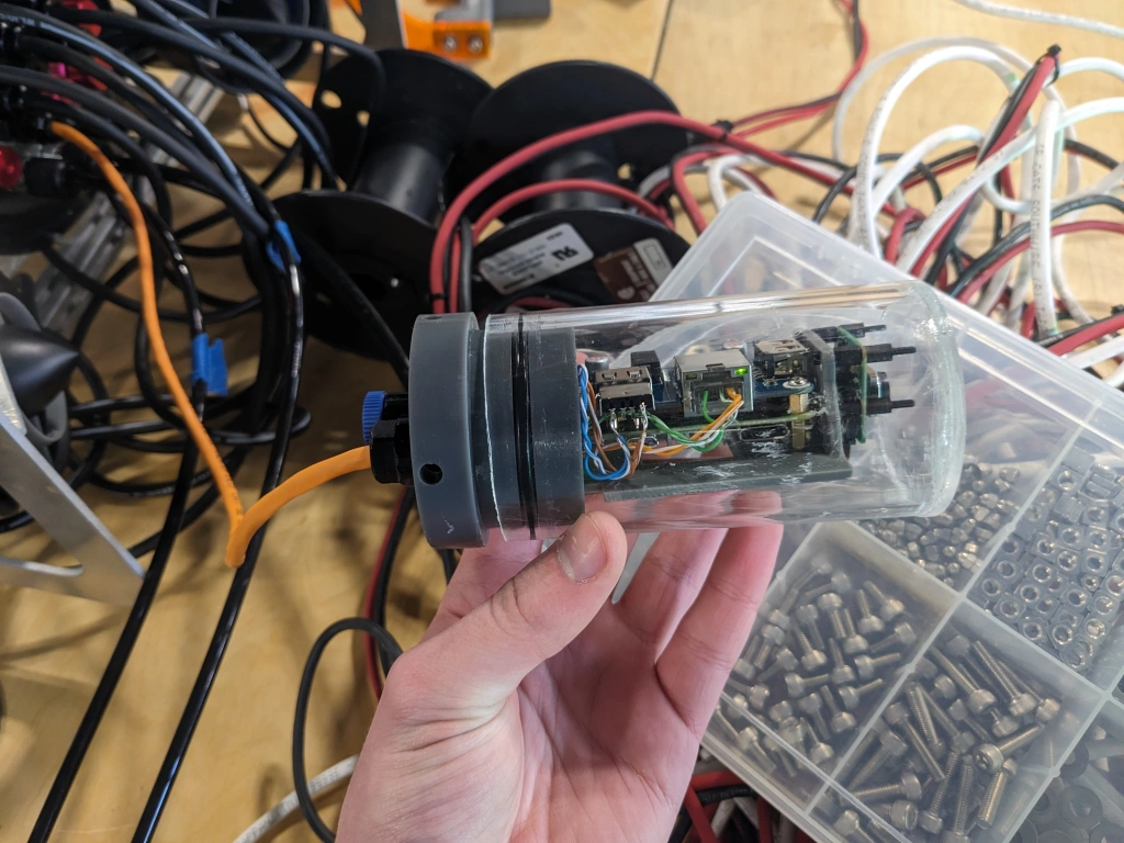
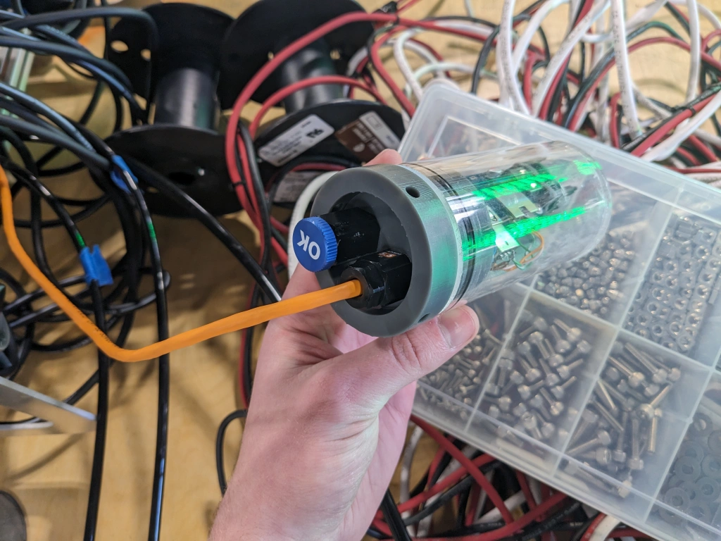
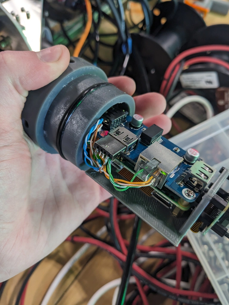
During our 2022-2023 year, although the Tube Cameras worked well, the way they had two separate wires for each one was a big hassle and a major point of failure. I revised the way they’re connected to the Main Electronics Tube and have combined both 5V power and 100Mbps ethernet into a single CAT 5E cable. The Tube Cameras never utilized the full 1Gbps they were wired with on S.T.E.V.E., so I repurposed the unused twisted pairs into 5V power and GND.
See posts about JONA ROV's Cameras
2022-2023
Tube Camera:
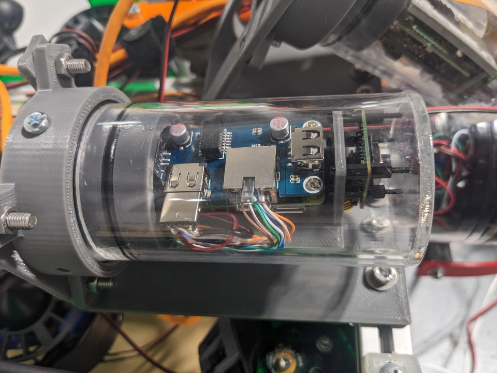
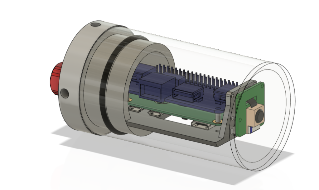
During our 2022-2023 year, we made two major improvements to S.T.E.V.E.: The gripper and the camera system. I focused on cameras for almost the entirety of the year and designed a multitude of cameras, but ultimately we decided one standard camera design was best. I focused my attention on the best design I’d made, which was the Tube Camera. The Bottom Camera was, for many reasons, a bad design, but the worst aspect of it was how long it took to disassemble and reassemble. The fasteners used to attach the face plate took a very long time to put together. This made maintenance very difficult. The Tube Camera, however, utilizes a custom O-ring seal instead of fasteners. This drastically reduced the time it took to put together, and was a major improvement. It was also far smaller, so it could feasibly be mounted facing forward and backward instead of exclusively down. The Tube Camera is still in use on JONA ROV.
2021-2022
Electronics Tray:
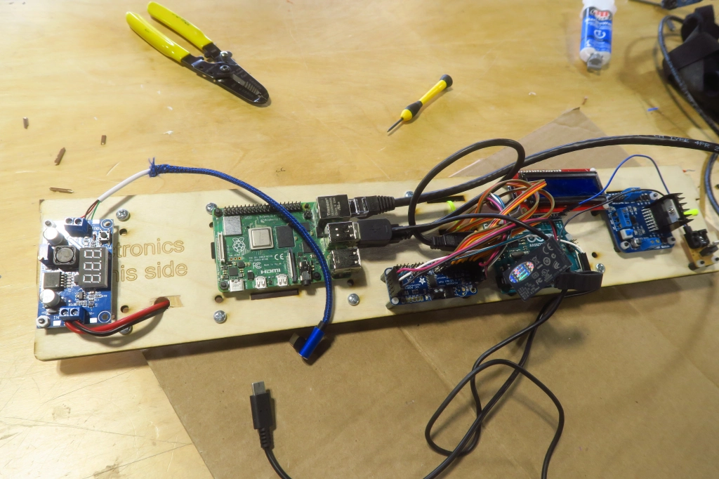
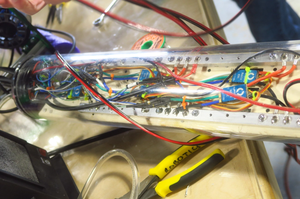
I designed the electronics tray for S.T.E.V.E. ROV, which would be used from 2021-2023. The tray contained all of the electronics (other than the external Bottom Camera) for the ROV. Being made from laser-cut 1/4in plywood, it was very adaptable, as new holes could easily be drilled without disassembling the entire thing.
Bottom Camera:
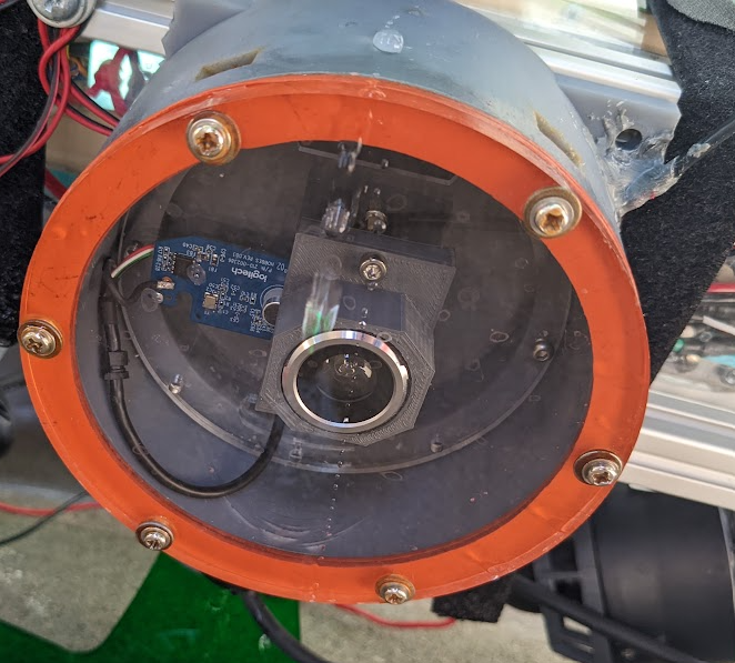
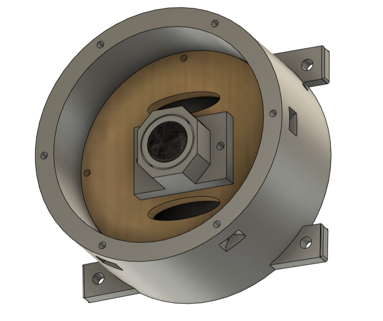
After the 2021 regional, we realized that we needed a bottom-facing camera. I was tasked with making this bottom camera. I was not very experienced and decided to create a waterproof housing around a camera design I’d already made and implemented. This solution was very inefficient and clunky, but it did work.
Light:
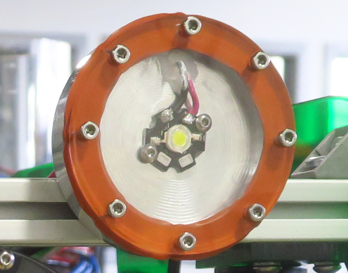
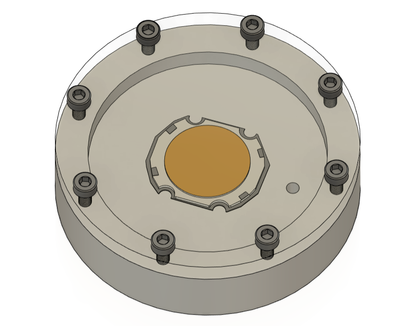
During our first year, before we had actually attended any competitions, we weren’t quite sure what the lighting conditions of the pools we’d be competing in would be. We decided to add a light to the front of the ROV so that we’d be able to see in low-light conditions. We quickly realized that we’d only be competing in well-lit environments and decided not to use the light as it could only cause additional problems and we did not require it. This was my first contribution to the Robotics Team.
Micromouse:
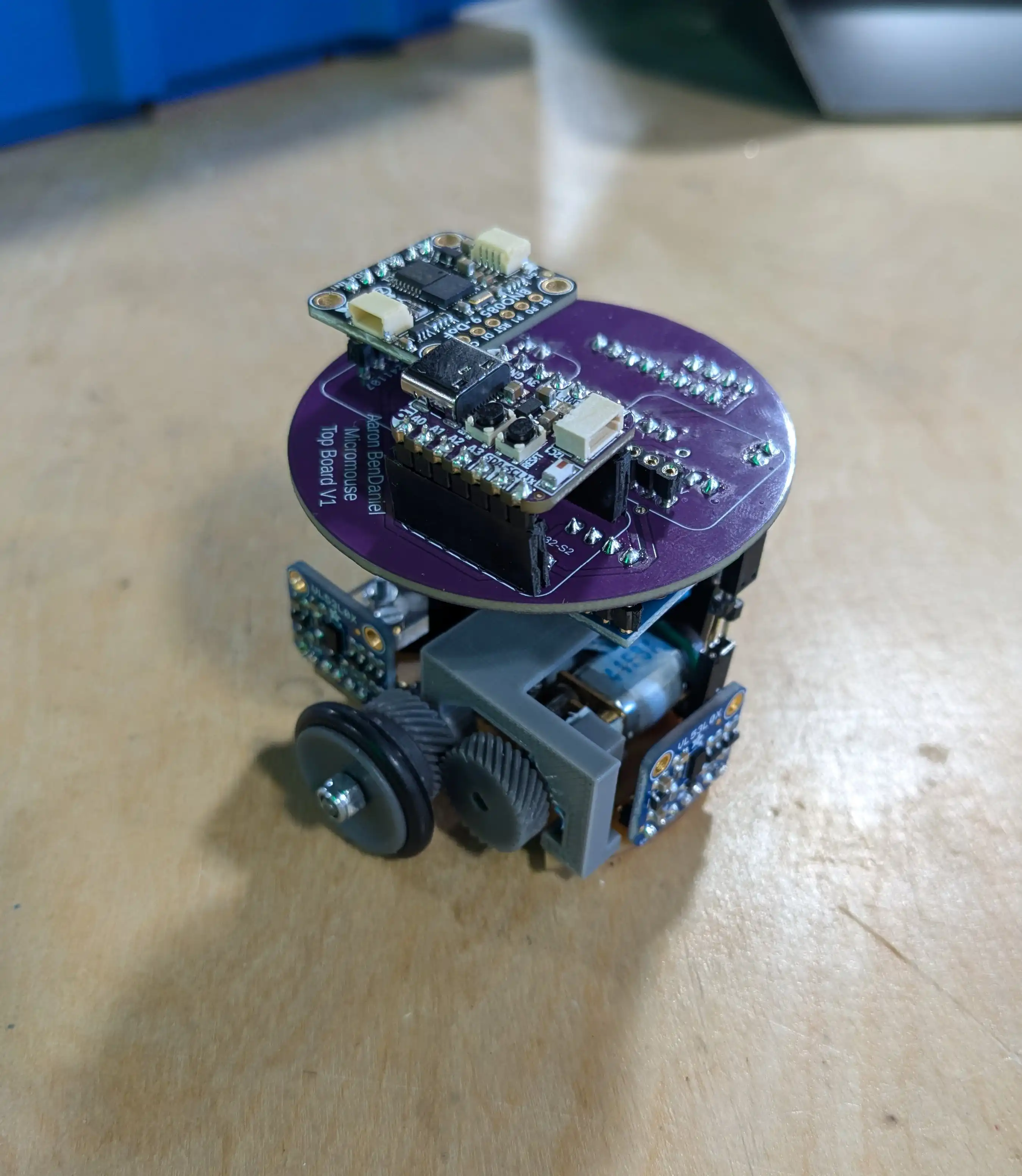
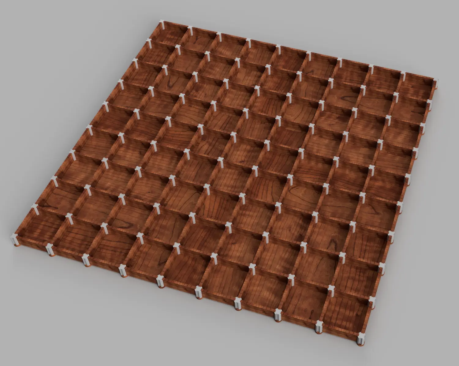
So far in my senior year at MVTHS, my main project has been constructing a Micromouse. Micromice are small maze-solving robots that are placed in a maze, allowed to explore a little bit, and then try to get from the start to the finish as fast as possible. I’m building a half-scale Micromouse, which is, as the name might suggest, half the size of a typical Micromouse. Each cell in the maze it must traverse is 9cmx9cm, which means that the robot must be quite compact and this posed a number of challenges for me.
I have finished the hardware and pathfinding algorithm for the robot, and am currently working on the hardware-interface code and getting it’s movements as precise as possible. The robot has two DC motors, an encoder on each motor, a BNO085 9-axis IMU, and three VL53L0X Time of Flight sensors.
It features an Adafruit QT-PY ESP32-S2 microcontroller, which is completely overkill for this project, but it’s super small and while I did try, I ultimately failed at getting my pathfinding algorithm to run on an ATMEGA328.
See the code for my Micromouse on Github
See posts about my Micromouse
The Sumo Bot Project:
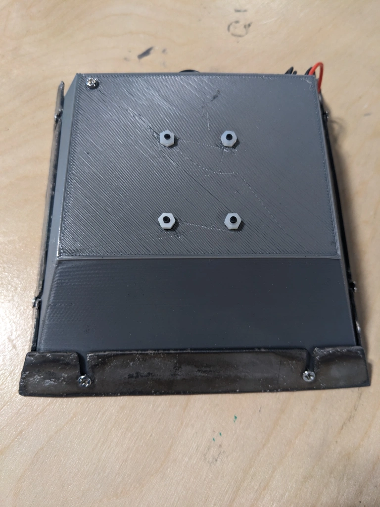
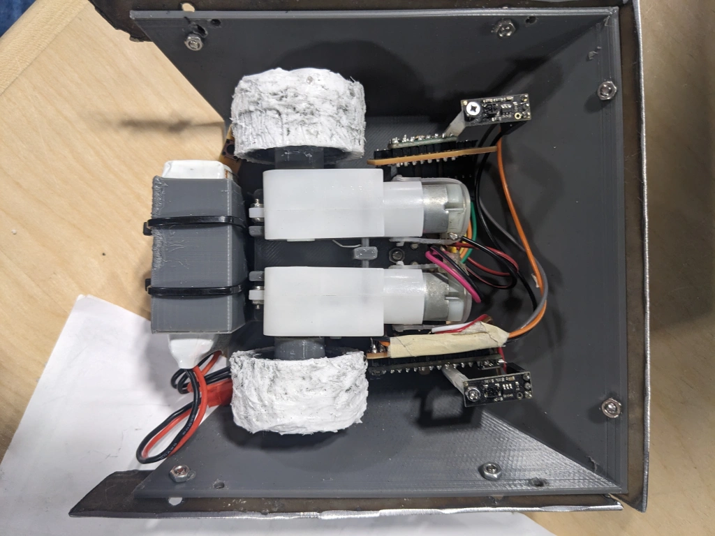
All sophomores in the Robotics & Engineering vocational shop participate in the Sumo Bot Competition. Students are broken up into teams of 1-2 people and they have a few weeks to build a sumo bot to compete. My partner, Tanzerul Azam, and I formed “Team Nestle” and built a sumo bot.
The Lightbox Project:
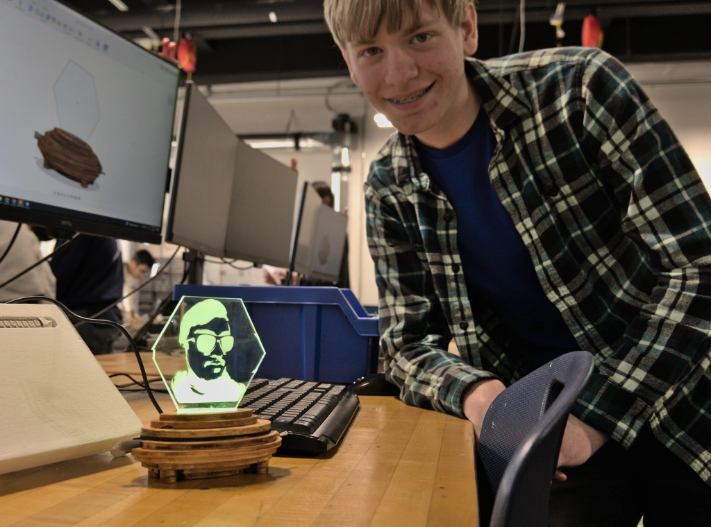
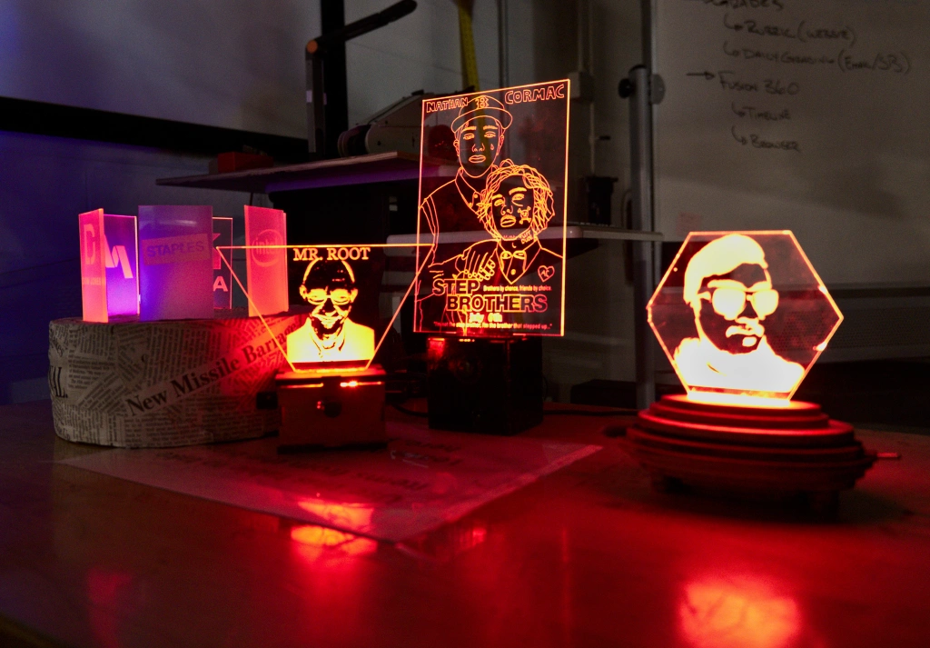
Left-to-right: Scott Campbell ('25), Tanzerul Azam ('25), Nate Matarazzo ('25), Aaron BenDaniel ('25).
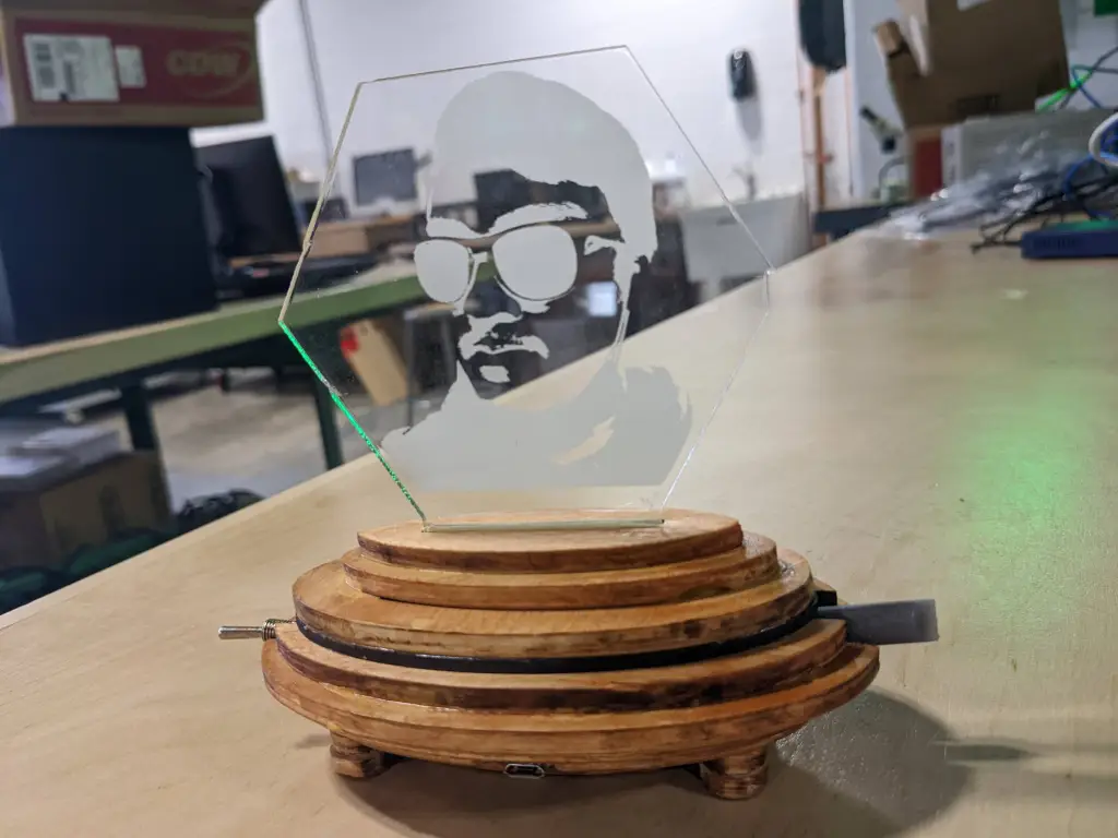
All sophomores in the Robotics & Engineering vocational shop are tasked to build lightboxes during the second quarter of their year. I decided to build a wooden ellipsoid lightbox. It has a hexagonal display that features the face of one of my classmates, Tanzerul Azam. The lightbox can be controlled using the switch and potentiometer on the sides.
My lightbox has a variety of display modes:
- Solid color (#000000 to #FFFFFF)
- Random Color
- Rainbow
- Strobe
Eccentric Staircase:
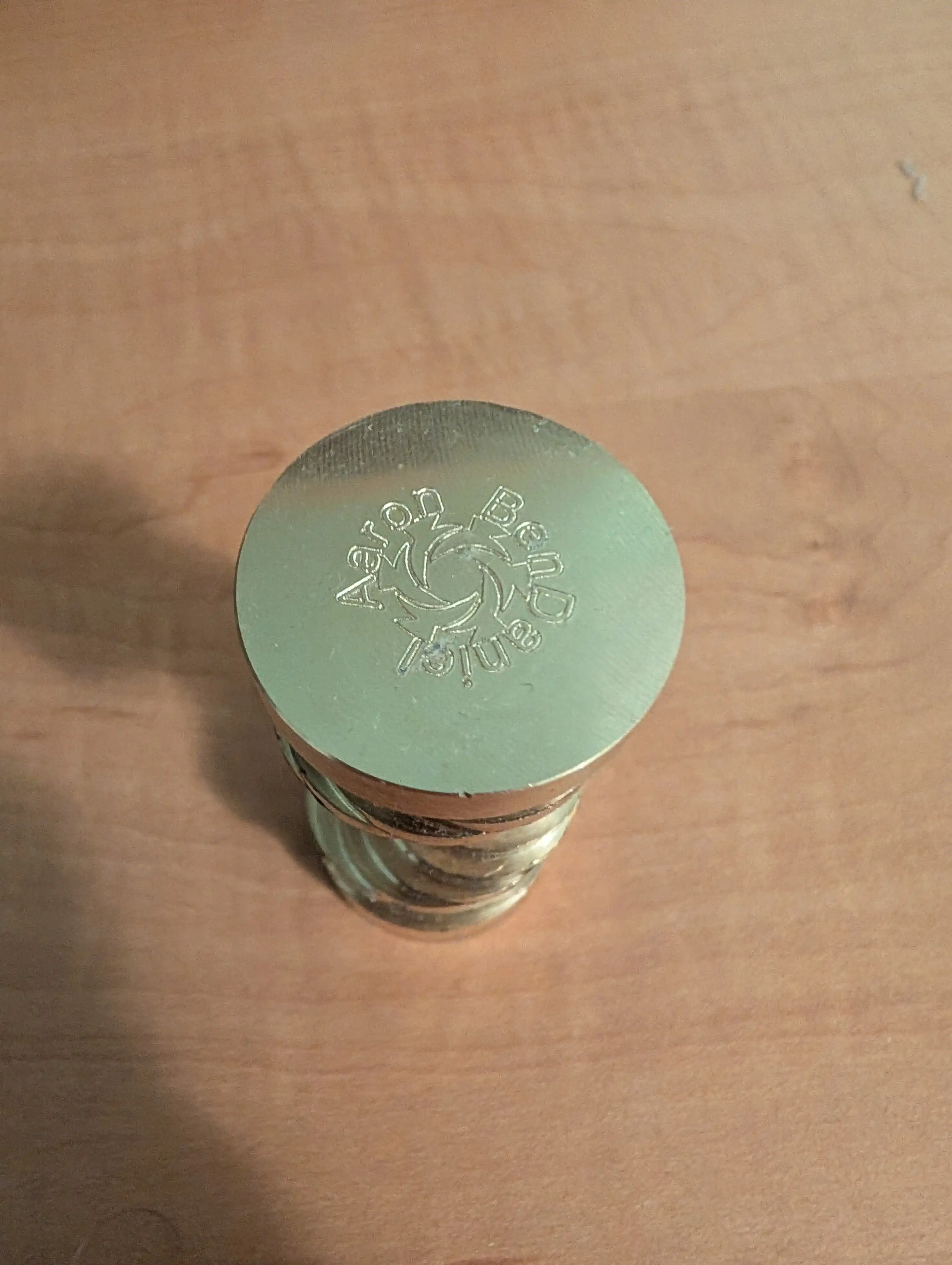
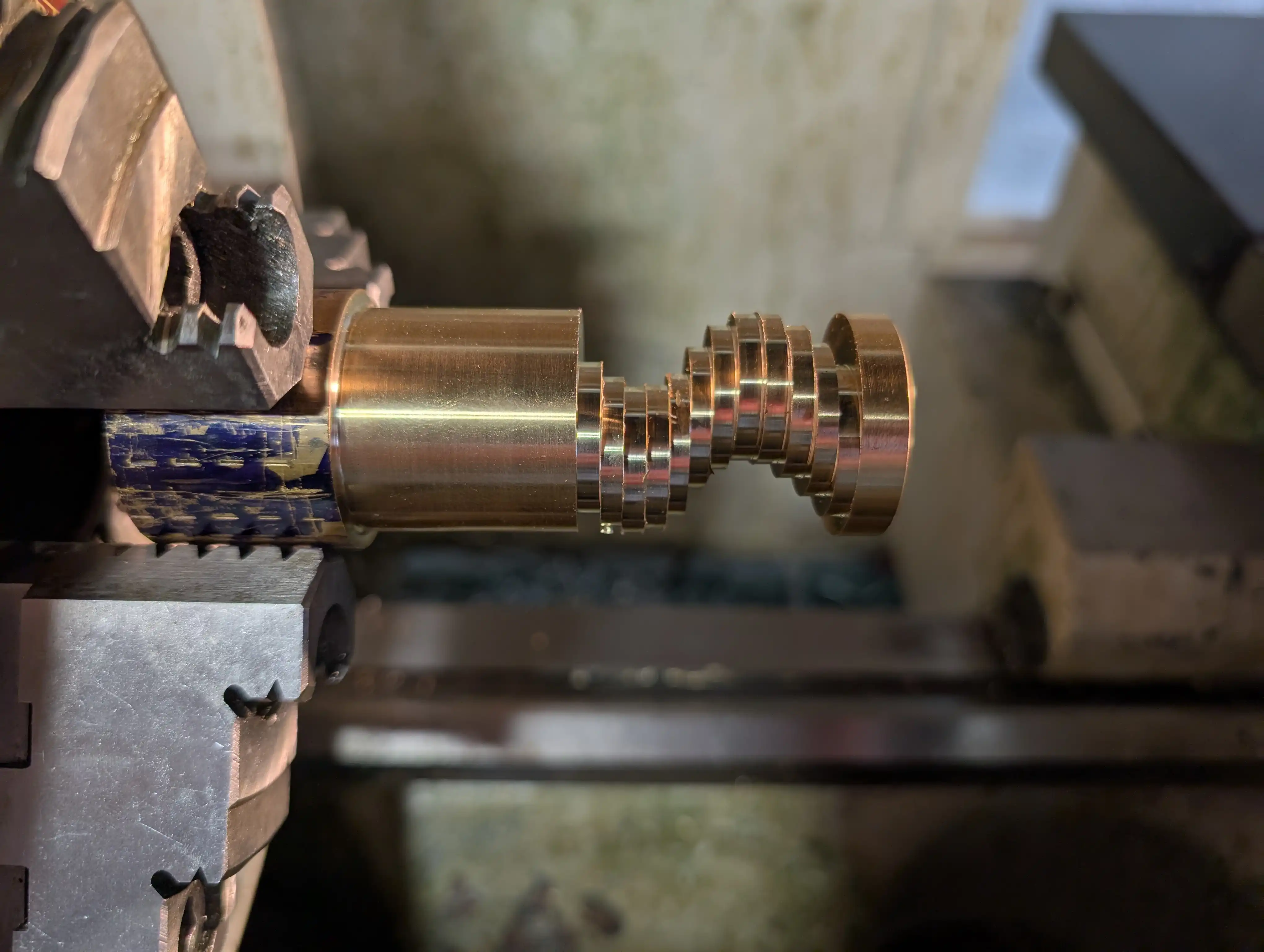
My eccentric staircase was the last project I did in the Robotics & Engineering shop. I wanted to make something that looked interesting, and keeping with the theme I had set, wanted it to be a machining project. I had seen a similar project online and was inspired to make my own.
See posts about my Eccentric Staircase
Tap Follower:
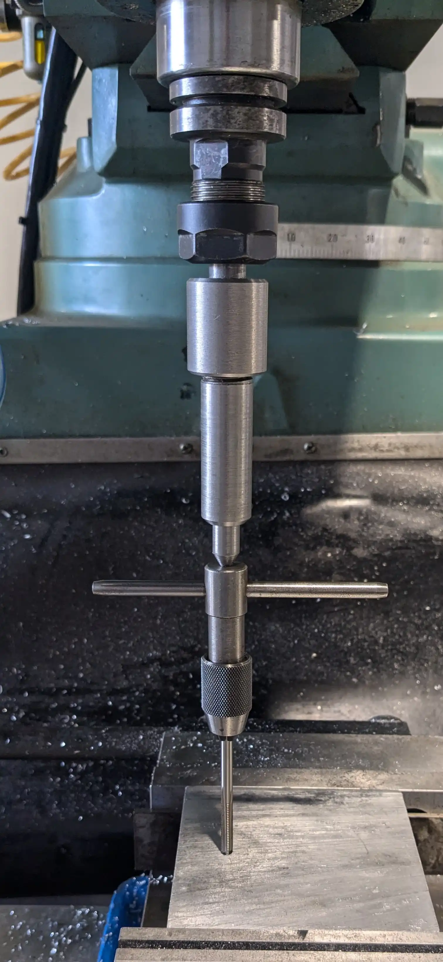
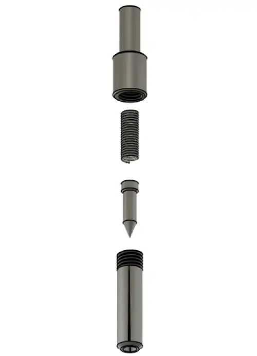
During my Micromouse project, I was getting frustrated with my slow progress and decided to take a break. I chose to start a machining project and decided to build a tap follower.
A tap follower is a tool to help center a thead-cutting tap and apply constant pressure. It makes cutting threads with taps significantly easier.
See posts about my Tap Follower
Machinist’s Jack:
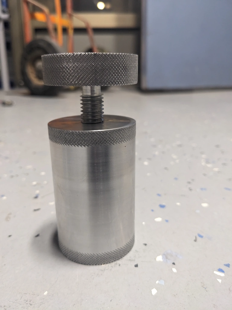
This was a project that I started near the end of my Sophomore year. I designed it and began turning it, but ultimately failed in my attempt. I made my second attempt mid-way through Junior year, and succeed the second time after having learned from my mistakes the first time I attempted this project.
I was suggested the idea to make a Machinist’s Jack by Mr. L after having one would have been helping when milling my Dead Tool Rack. It is a tool to help give additional support to a part when milling it. So far I have only made one of these, but I might make a second in the future.
See posts about the Machinist's Jack
Tool Post Bearing:
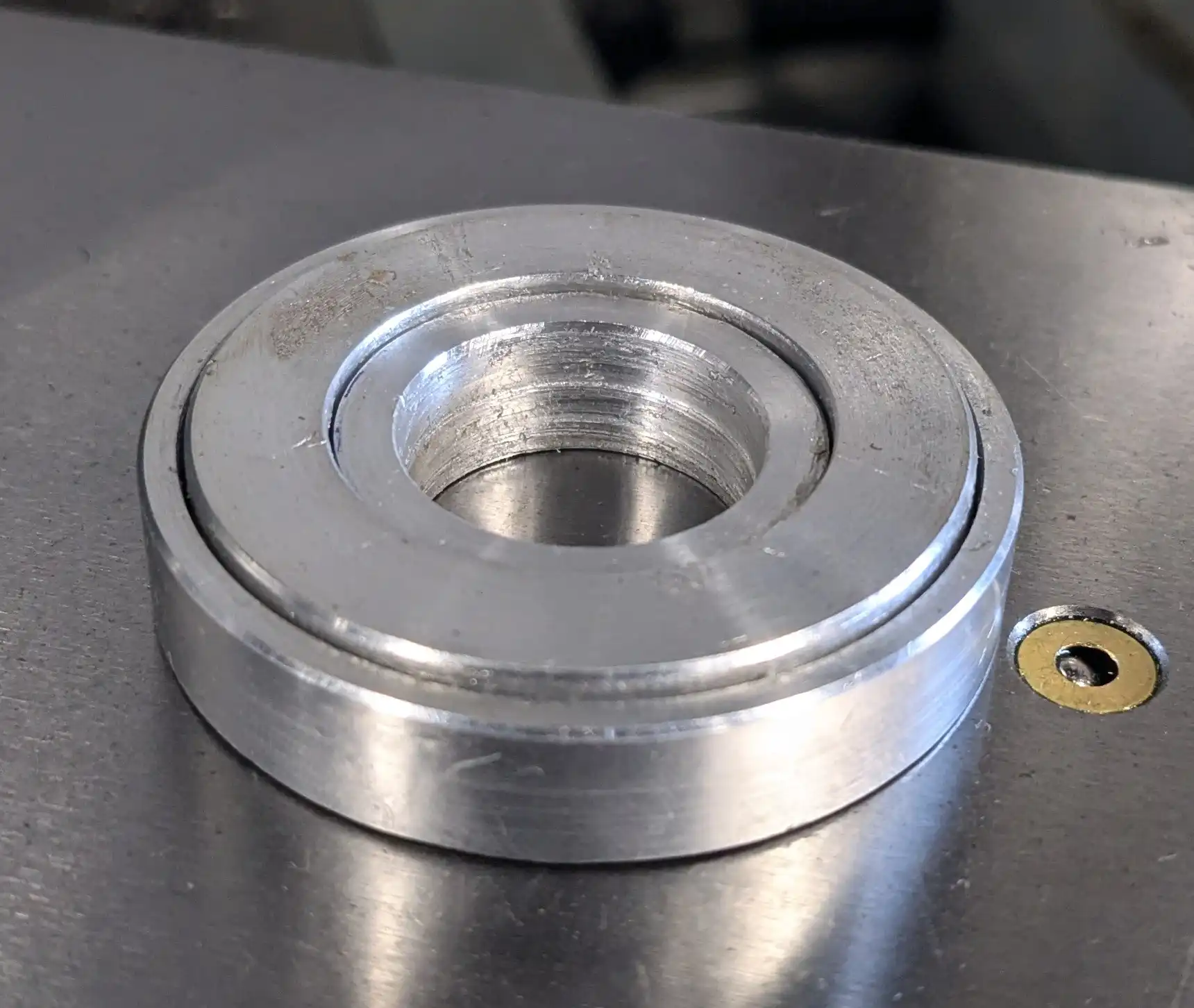
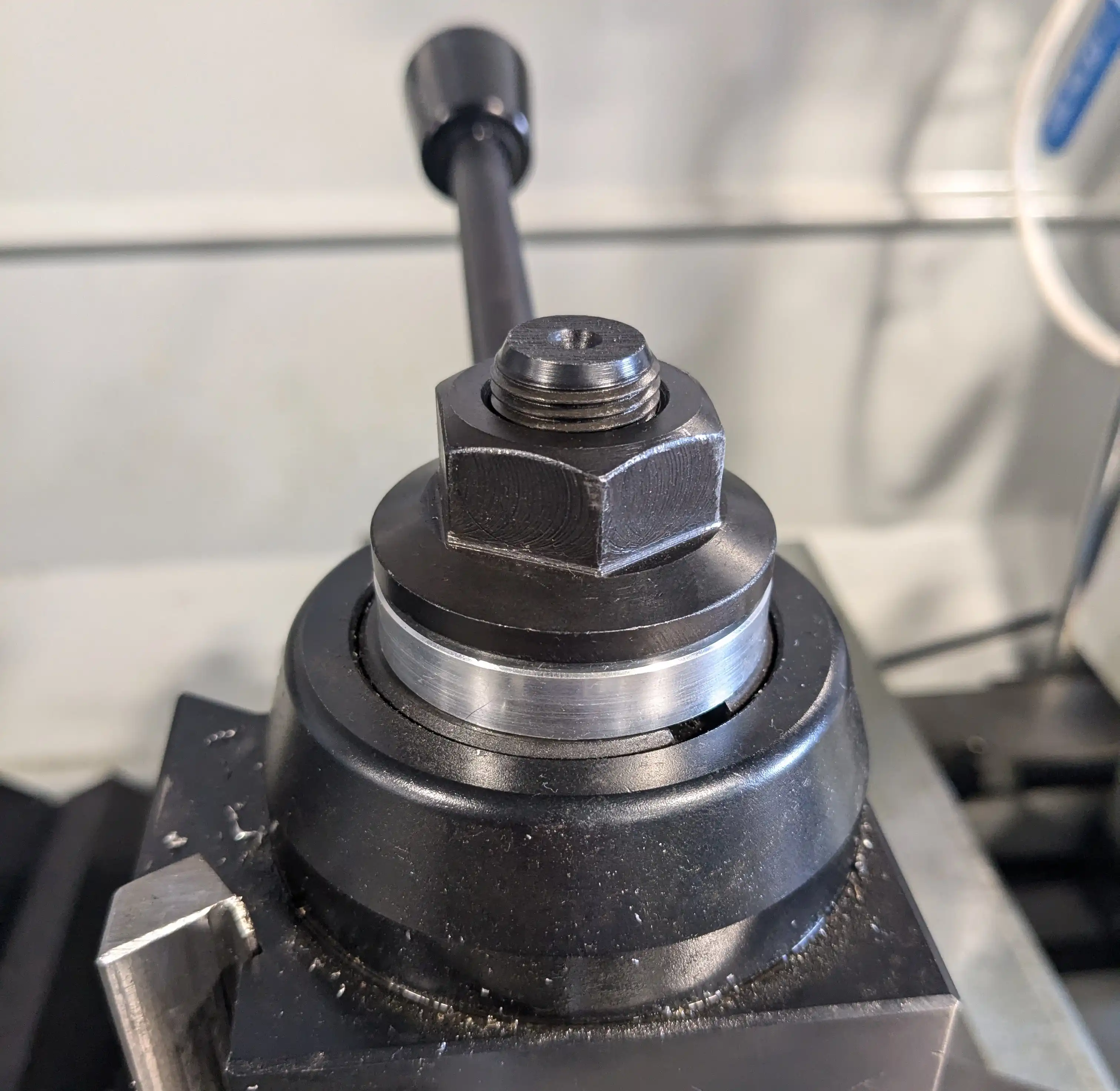
After I finished the Tap Follower, I still wanted to continue my break from my Micromouse project and decided to make yet another addition to the machine shop.
This bearing sits between the South Bend Lathe’s tool post and the bearing that holds it down. It eliminates friction between the two and without it, the tool post rotates out of alignment when tightening it down. This bearing makes aligning the tool post a significantly faster task and a lot less frustrating.
Ben Wirz recommended this project to me.
Metal Head:
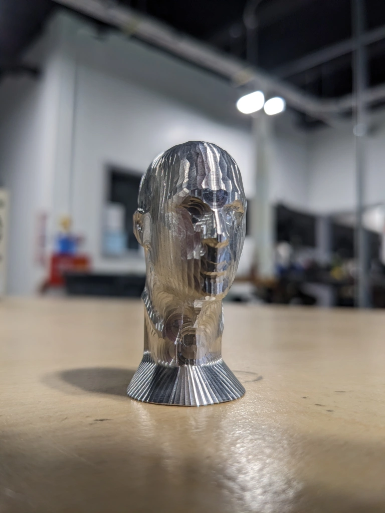
Near the end of my sophomore year in the Robotics & Engineering shop, I wanted to learn more about our Tormach PCNC 1100 4th axis extension. I decided that I wanted to mill a complex 3D object and settled on a portrait bust of a human head.
Metal Die:
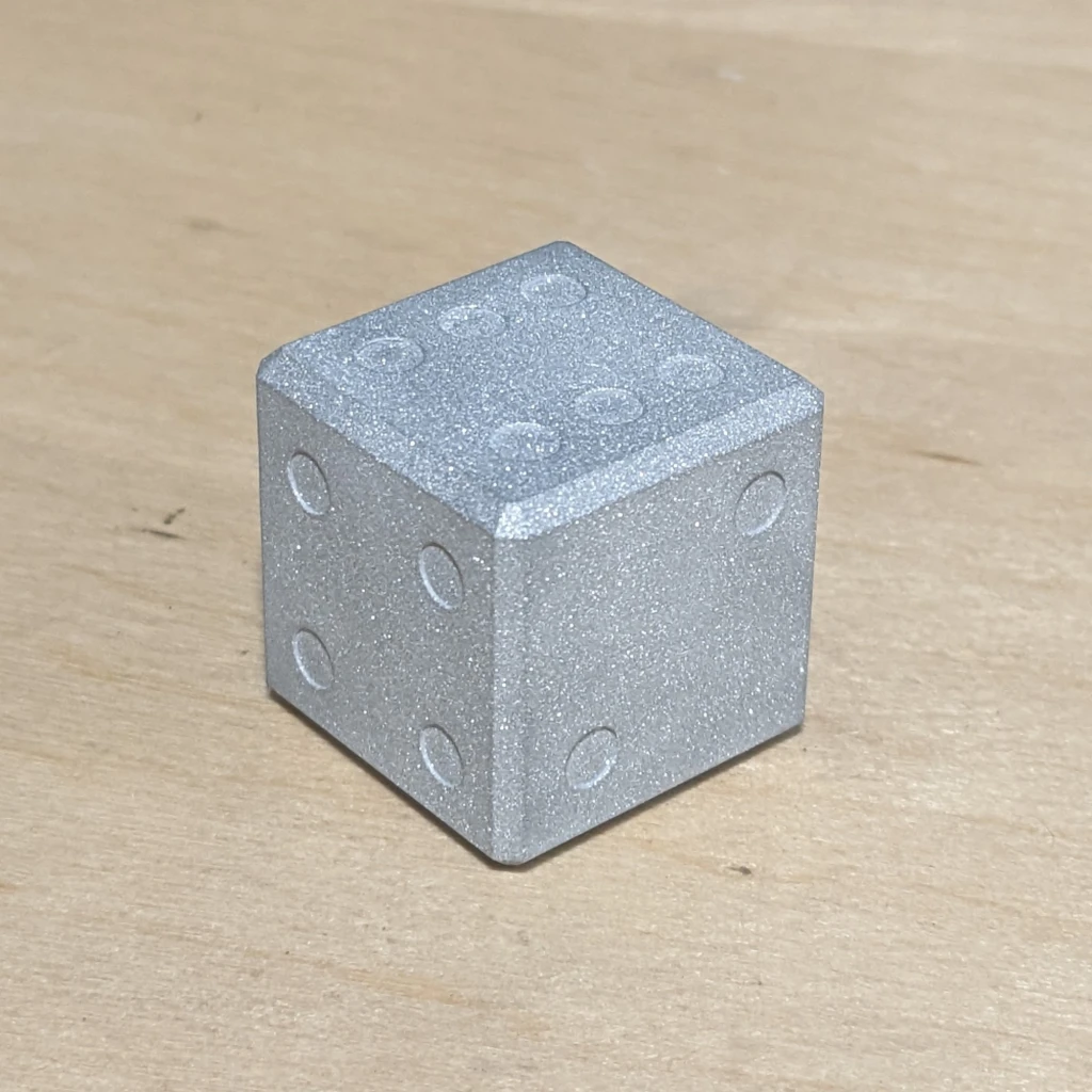
Before I started on my Metal Head project, one of my Robotics teachers, Noah Lewkowitz (Mr. L) asked me if I wanted to finish a project he had started. Mr. L had begun to work on a metal six-sided die, and I decided to finish it. The die honestly isn’t that great and I have a few modifications I would make if I milled another one, but at the moment I do not have plans to make another one. Maybe I’ll eventually mill a whole RPG dice set, but that’s a plan for the future.